DCC - Advanced Operations
LACC
LACC is a new firmware file that provides the DCC Booster and DCC Stationary Decoder functionality.
In order for LACC to work, the RCX needs to be connected to the track with the "Advanced Acknowledgement Circuit."
This sensor gets hooked from the track (or directly from the Command Station) to sensor port 1 of the RCX running LACC.
RCX Stationary Decoder
The DCC Stationary Decoder function is provided by the new LACC firmware file. Stationary Decoder mode allows you to control up to three motorized switches. You can control the switches via the RCX remote control or through the LDCC IR Protocol (described below).
When you first download the LACC firmware, it starts up in Stationary Decoder mode. You will know you're in Stationary Decoder mode when an uppercase A shows up in right hand side of the lcd panel (the A stands for Accessory).
Hookup sensor port 1 to the track using the sensor described in the LACC section above. Each individual output of the RCX goes to a seperate motorized switch. By default, LACC is setup to control switches 1 through 3. To control other switch numbers, you need to configure LACC's base address:
- From Standby, press [View] repeatedly until the display reads Addr, then press [Prgm].
- Press [Prgm] (or the remote control arrow keys) to change the base address.
- To exit, press [Run] or [Stop] repeatedly until you're back in Standby.
Switches 1-5 are controlled by the [P1]-[P5] keys on the RCX remote control. Switches 6-10 are controlled by holding down the Beep key and pressing [P1]-[P5]. Switches greater than 10 can be controlled using the LDCC IR Protocol.
RCX Booster
The DCC Booster function is provided by the new LACC firmware file.
To use the RCX as a booster, you insulate your layout into two or more "power districts". You attach the Command Station (the RCX running LDCC) to one district, and one or more RCXs (running LACC in Booster mode) to the remaining sections.
The three outputs of the Booster RCX can be tied together in parallel and hooked to the corresponding insulated section of track in the same fashion as the Command Station. Caution: Only the three outputs from the same booster RCX are tied together in parallel. The outputs of multiple booster RCXs must be kept insulated from one another.
Sensor port 1 is hooked to the track powered by the Command Station using the sensor as described in the LACC section above.
When insulating the various sections of your layout, I strongly recommend you use the 5cm gap insulation technique described in this thread on Lugnet. I prefer the tape method that Dean Husby talks about. It's much more tolerant of slower trains (they won't stall as easily) and it's not a permanent modification.
Shorting the two RCXs (even momentarily) is best avoided, that's why I recommend against using just a pair of paper strips only. A train motor crossing this type of insulated track will short both power districts together.
Make sure the power supply to your RCX isn't a "switching" type wall adapter. Just use a standard train wall adapter.
When you first download the LACC firmware, it starts up in Stationary Decoder mode. To activate Booster mode:
- From Standby, press [View] repeatedly until the display reads boSt.
- Press [Prgm], then [Run].
You will know you're in Booster mode when a lowercase b shows up in right hand side of the lcd panel.
LACC will remain in Booster mode until you switch it back to Stationary Decoder mode. If you turn the RCX off, then when you power it back on you will need to press Run again.
To switch back to Stationary Decoder mode:
- From Standby, press [View] repeatedly until the display reads AccY.
- Press [Prgm], then Run.
LDCC IR Protocol
This is a new feature for the LDCC Command Station firmware. It's a special set of IR commands that allow LDCC to be controlled remotely by another RCX or PC program. Right now, the best documentation for the protocol is the two demo programs included in the zip file or checking out the Example Code Section.
Tethered Throttle
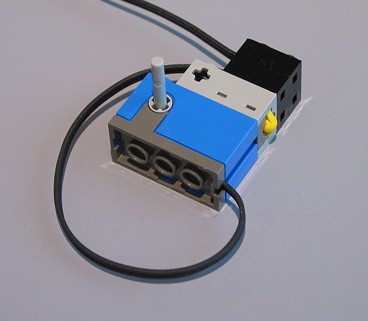
Here's a simple rotation sensor throttle with one button:

To setup a rotation sensor as a tethered throttle in LDCC:
- From Standby, press press [View] repeatedly until the display reads SEnS, then press [Prgm].
- Press [Prgm] repeatedly until the desired sensor port is shown on the right hand side of the display, then press [View].
- Press [Prgm] repeatedly until rot is shown in the display, then press [View].
- Press [Prgm] repeatedly until the desired Loco # to control is displayed, then press [View].
- Press [Prgm] once to set the number of buttons to one, then press [View].
- Press [View] again to skip Func.
- Press [Prgm] or use the remote arrow keys to change the number of rotation steps needed for full throttle. The default is 32 which represents two full turns of the rotation sensor. Press [View] to continue.
- Press [Prgm] if you want to reverse the direction of the throttle. This swaps reverse for forward (if necessary) to make operating the throttle more natural.
- To exit, press [Run] or [Stop] repeatedly until you're back in Standby.
Pressing the button briefly (for about 1/4 second) toggles the locomotive's headlight on and off. Holding the button down for longer stops the locomotive.